This is default featured post 1 title

Go to Blogger edit html and find these sentences.Now replace these sentences with your own descriptions.

This is default featured post 2 title

Go to Blogger edit html and find these sentences.Now replace these sentences with your own descriptions.

This is default featured post 3 title

Go to Blogger edit html and find these sentences.Now replace these sentences with your own descriptions.

This is default featured post 4 title

Go to Blogger edit html and find these sentences.Now replace these sentences with your own descriptions.

This is default featured post 5 title

Go to Blogger edit html and find these sentences.Now replace these sentences with your own descriptions.

Friday 3 August 2012

OSI models | Open Systems Interconnection - OSI layers - Networking layers | Seven layers of network

The OSI Model is used to describe networks and network application. The OSI model is a technology standard maintained by the International Standards Organization (ISO). Although today's technologies do not fully conform to the standard, it remains a useful introduction to the study of network architecture.

  • ISO(International Standards Organization) is a multinational bogy dedicated to worldwide agreement on international standards.
  • Layers :--

 
Physical Layer

  • Physical characteristics of interfaces and media: The physical layer defines the characteristics of the interface between  devices and the transmission media, including its type.
  • Representation of the bits: the physical layer data consist of a stream of bits  without any interpretation. To be transmitted, bits must be encoded into signals –electrical or optical-. The physical layer defines the type of encoding.
  • Data rate: The physical layer defines the transmission rate, the number of bits sent each second.
  • Line configuration:  the physical layer is concerned with the connection of devices to the medium.
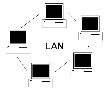
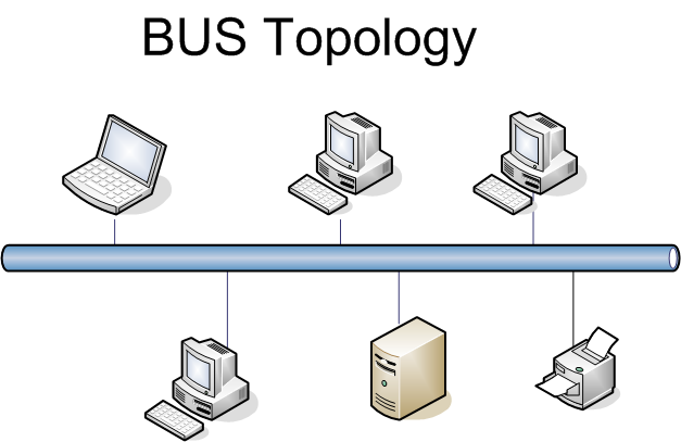
  • Physical topology
  • Transmission Mode
Data Link Layer


  • Framing. The data link layer divides the stream of bits received from the network layer into data units called frames.
  • Physical addressing. If frames are to be distributed to different systems on the network, the data link layer adds a header to the frame to define the physical address of the sender (source address) and/or receiver (destination address) of the frame.
  • Error control.  The data link layer  adds reliability to the physical layer by adding mechanisms to detect and retransmit  damaged or lost frames. Error control is normally achieved through a trailer to the end of the frame.
  • Access Control. When two or more devices are connected to the same link, data link layer protocols are necessary to determine which device has control over the link at any time.

Network Layer

  • Logical addressing. The physical addressing implemented by the data link layer handles the addressing problem locally.
  • The network layer adds a header to the packet coming from the upper layer, among other things, includes the logical address  of the sender and receiver.
  • Routing. When independent networks or links are connected together to create an inter network (a network of networks) or a large network, the connecting devices (called routers or gateways) route or switch the packets to their final destination.
Transport Layer

  • Port addressing: computer  often run several processes (running programs) at the same time.
  • Process-to-process delivery means delivery from a specific process on one computer to a specific process on the other.
  • The transport layer header include a type of address called port address.
  • Connection control: The transport layer can be either connectionless or connection-oriented.
  • A connectionless transport layer treats each segment as an independent packet and delivers it to the transport layer at the destination machine.
  • A connection-oriented transport layer makes a connection with the transport layer at the destination machine first before delivering the packets. After all the data are transferred, the connection is terminated.
  • Flow control:  the transport layer performs a flow control end to end. The data link layer performs flow control across a single link.
  • Error control: the transport layer performs error control end to end. The data link layer performs control across a single link.
Session Layer

  • The services provided by the first three layers are not sufficient for some processes.
  • The session layer is the network DIALOG CONTROLLER.  It establishes, maintains, and synchronizes the interaction among communication systems.
  • Dialog control:  The session layer allows two systems to enter into a dialog.  It allows the communication between two processes to take place in either half-duplex of full-duplex mode.
  • Synchronization:  The session layer allows a process to add checkpoints, or synchronization points, to a stream of data.
Presentation Layer
  • The presentation layer is concerned with the syntax and semantics of the information exchanged between two systems.
  • Network process to application
  • The presentation layer is responsible for translation, compression and encryption.
  • Translation:  The process in two systems are usually exchanging information in the form of character strings, numbers, and so on.  The information must be changed to bit streams before being transmitted.  Because different computers use different encoding systems, the presentation layer is responsible for interoperability between these different encoding methods. 
  • The presentation layer at the sender changes the information from its sender-dependent format into a common format.  The presentation layer at the receiving machine changes the common format into its receiver-dependent format.
  • Encryption:  To carry sensitive information, a system must be able to ensure privacy.
  • Encryption means that the sender transforms the original information to another form and sends the resulting message out over the network.  Decryption reverses the original process to transform the message back to its original form.
  • Compression:  It reduces the number of bits contained in the information.  In multimedia such as text, audio, and video.
Application Layer

  • It is responsible for providing services to user.
  • FTP, mail services, directory services.


Tuesday 31 July 2012

Wide Area Network | WAN in networking | Types of Network - WAN

 A WAN spans a large geographic area, such as a state, province or country. WANs often connect multiple smaller networks, such as local area networks (LANs) or metro area networks (MANs).


For home routers the port the router connects to your Internet connection is often labeled as a WANNetworkor Internet port, since it is what allows your home network to communicate with the Internet network. In the below picture, is an example of the Internet port on the back of a home router, next to four standard Ethernet ports.

Numerous WANs have been constructed, including public packet networks, large corporate networks, military networks, banking networks, stock brokerage networks, and airline reservation networks. Some WANs are very extensive, spanning the globe, but most do not provide true global coverage. Organisations supporting WANs using the Internet Protocol are known as Network Service Providers (NSPs). These form the core of the Internet. 


Messages can be sent very quickly to anyone else on the network. These messages can have pictures, sounds, or data included with them (called attachments).

Expensive things (such as printers or phone lines to the internet) can be shared by all the computers on the network without having to buy a different peripheral for each computer.


Metropolitan Area Network | MAN in networking | Types of Network - MAN

A Metropolitan Area Network (MAN) is a network that interconnects users with computer resources in a geographic area or region larger than that covered by even a large local area network (LAN) but smaller than the area covered by a wide area network (WAN).


A large computer network which extends to a city or to a large university campus is termed as metropolitan area network or MAN.  The purpose of MAN is to provide the link to the internet in the long run. A MAN (Metropolitan Area Network) usually incorporates a number of LANs to form a network. This large network MANs (Metropolitan Area Network) backbone comprises of an optical fiber set-up.


This is a larger network that connects computer users in a particular  geographic area or region. For example a large university may have a network so large that it may be classified as a MAN.


MAN usually falls between LAN and WAN. It is generally applied to connect geographically dispersed LANs. Therefore the goal of MAN is to develop a communication link between two independent LAN nodes. A MAN (Metropolitan Area Network) is usually established using optical fiber. The network is established using routers and switches. A switch is a port which is active in handling the filtration of data usually coming in the form of frames.  Any switch acts as a dual port, at one end it is handling filtration of data and at the other end managing connections. Router is another device for facilitating the netwosrk connection. Router helps the data packets to identify the path to be taken. Hence in other words it keeps an eye on the data transfer. MAN (Metropolitan Area Network) is usually operated over an area of up to 50kms.

Local Area Network | LAN in networking | Types of Network - LAN

A local Area Network (LAN) is a group of computers and associated devices that share a common communications line or wireless link.


A LAN usually connects servers, workstations, printers, and mass storagedevices, enabling users toshare the resources.

Most local area network share built with relativelyinexpensive hardware suchas Ethernet cables, network adapters, and hub.


LAN characteristics are determined by:

Topologies
 MAC (Medium Access Control)
 Transmission media
 Size of coverage

LAN Interconnection

Traditional LAN interconnection devices


Repeater – it operates at OSI layer 1 and transmits data bits over a physical medium. 
Bridge – it operates at OSI layer 2 and is commonly used to connect similar LAN segments.
Switch – it operates at OSI layer 2 or layer 3 and is used to interconnect multiple similar or dissimilar LANs.
Router – it operates at OSI layer 3. A router is used to interconnect  individual networks whose sizes vary from very small to very large. Routers may be categorized into backbone router (or core router), border router and access router depending on their role in the network.


Friday 27 July 2012

Topology | Types of Topology - Define Topology | Bus - Star - Ring - Mesh - Hybrid Topology in networking. | Structure - Working of Topology


"The physical layout or the way in which network connections are made is known as topology."

Following are network topologies.
1) Bus topology
2) Star topology
3) Ring topology
4) Mesh topology
5) Hybrid topology

1. BUS TOPOLOGY :

STRUCTURE of Bus Topology

A star topology is designed with each node (file server, workstations, and peripherals) connected directly to a central network hub, switch, or concentrator.
Data on a star network passes through the hub, switch, or concentrator before continuing to its destination. The hub, switch, or concentrator manages and controls all functions of the network. It also acts as a repeater for the data flow. This configuration is common with twisted pair cable; however, it can also be used with coaxial cable or fiber optic cable.


WORKING OF Bus Topology

The computers that send data also attach address of the destination computer with the data. All computers connected to the bus receive the data but only that computer accept it whose address matches the address attached with data.
In this topology only one computer at a time can send a data therefore the speed of network reduces as the number of computers attached to the bus increases.

ADVANTAGES of Bus Topology
  • Easy to install and configure
  • Inexpensive
  • Easily extended 
Disadvantages of Bus Topology 
  • Performance decreases
  • Weak signals
  • Difficult troubleshooting

2. STAR TOPOLOGY :


"In star topology all the cables run from the computers to a central location, where they all are connected to a device called HUB."

WORKING OF Star Topology


Each computer in a star network communicates with the central hub that resents the messages either to all computers (in a broad cast network) are only to destination computer (in a switch network).
Star network maybe designed to operate in a polled mode where each user is asked in turn .if it has any information to transmit and in case, if it has, the communication controller will either give full attention to that device until it has no more information to send or it will allow the device to send part of its information ,give another device a chance and then return back to original device.

ADVANTAGES of Star Topology

  •  As compared to Bus topology it gives far much better performance, signals don’t necessarily get transmitted to all the workstations. A sent signal reaches the intended destination after passing through no more than 3-4 devices and 2-3 links. Performance of the network is dependent on the capacity of central hub.
  •  Easy to connect new nodes or devices. In star topology new nodes can be added easily without affecting rest of the network. Similarly components can also be removed easily.
  • Centralized management. It helps in monitoring the network.
  • Failure of one node or link doesn’t affect the rest of network. At the same time its easy to detect the failure and troubleshoot it.
DISADVANTAGES of Star Topology

  • Too much dependency on central device has its own drawbacks.
  •  If it fails whole network goes down.
  • The use of hub, a router or a switch as central device increases the overall cost of the network.
  •  Performance and as well number of nodes which can be added in such topology is depended on capacity of central device.

3. RING TOPOLOGY :

"Ring topology looks like the bus topology with connected ends.
But 
In functionality it is different."

WORKING OF Ring Topology
  •  Each computer is connected to the next computer in the form of ring.
  • Each retransmit what it receives from the previous computer.
  • The message flow in one direction.
  • Ring topology connects computers on a single circle of cable.
  • There is no terminated ends
  • Signals travel around the loop in one direction and pass through each computer.
  • Unlike bus topology, each computer acts like a repeater to boost the signal and send it to the next computer.
  • It is called endless topology.
  • In ring topology, data flows in ring and in clock-wise direction.
  • Ring topology is based on “Token Ring Mechanism”.

Token Passing
  • A token is passed around the network.
  • The computer that has token can transmit data.
  • Token is passed from computer to computer until it reaches to its destination.
  • The destination device returns an acknowledgement to the sender.
  • The destination device returns an acknowledgement to the sender.
  • The token is then given to another device, giving it ability to transmit.
  • The token is then given to another device, giving it ability to transmit
  • The sending computer modified the token, puts address with the data and sends it around the ring.
  • Data passed by each computer until it finds the computer with an address that matches.
  • Token is used as a carrier.
  • It is called token grab.
ADVANTAGES of Ring Topology
  • when the load on the network increases, its performance is better than that of Bus topology.
  • There is no need for network server to control the connectivity between workstations.
  • Additional components do not affect the performance of network.
  • Each computer has equal access to resource.
  • Token ring technology reduces the need of server or central hub to manage the workstations.
DISADVANTAGES of Ring Topology
  • If one node is disrupted then the whole network goes down.
  • Only one machine can transmit on the network at a time.
  • The failure of one machine will cause the entire network to fail.
4. MESH TOPOLOGY :

"The topology of a network whose components are all connected directly to every other component."

WORKING OF Ring Topology

For sending messages, check the cable connected into two devices. A message is send directly from sender to receiver because each one has individual and separate connection.


ADVANTAGES of Mesh Topology

  • Eliminates traffic problems in links sharing.
  • If one link becomes unusable, it does not incapacitate the entire system. Thus, act as robust.
  • It has privacy and security.
  • Point-to-point link make fault identification and fault isolation easy.
DISADVANTAGES of Mesh Topology
  • Difficult to install and maintain.
  • Expenisve.

5. HYBRID TOPOLOGY :

"A combination of two or more different topologies makes for a hybrid topology. When different topologies are connected to one another, they do not display characteristics of any one specific topology. "

WORKING OF Hybrid Topology
The Hybrid topology scheme combines multiple topologies into one large topology.The hybrid network is common in large wide area networks. Because each topology has its own strengths and weaknesses, several different types can be combined for maximum effectiveness.

ADVANTAGES of Hybrid Topology
  • Any topology can be combined with another without making any changes to existing topology.  The speed of the topology is compatible because it combines the strengths of each of the topologies, eliminating weaknesses.  It is also more efficient.
DISADVANTAGES of Hybrid Topology

  • Installation and configuration of topology is difficult.  Because there are different topologies that need to connect.  At the same time, make sure none of them fail, which makes installation and configuration very difficult.


Thursday 26 July 2012

Computer Networks | Computer Network Definition | Uses - Computer Networking Overview - Business Application - Home Application - Social Issues.

"The old model of a single computer serving all of the organization's computational needs has been replaced by one in which a large number of separate but interconnected computers do the job.  These systems are called computer networks."


USES:

Business Applications

Client will send the packet to the Server via network.


Home Application

Access to remote information.
Person to Person Communication.
Interactive entertainment.
Electronic Commerce                                                                                                    


Social Issues

Newsgroups or bulletin boards


Access to Remote Information

Access to remote information occurs in many forms. One of the areas where it is happening is access to the financial institutions. Many people pay their bills, manage bank accounts and handle investments electronically. Home shopping is also becoming popular these days.

Another application that falls under this category is the access to information systems like World Wide Web which contains information about art, business, history, government, geography, economics and several other topics.

All the above applications involve the interaction between the user and a remote database.


Person to Person Communication

Electronic Mail popularly known as email is widely used by millions of people to send text messages, photographs audio as well as video to other people or group of people. This application belongs to person to person communication category.

Videoconferencing is also becoming popular these days. This technology makes it possible to have virtual meetings among far flung people. It is also a type of person to person communication.

Interactive Entertainment

These days we can see many live programmes and shows. The best thing is that we can interact with them by participating in the quizzes and the contests organized by them.
 

Networking History

Networking History
  • Each of the past three centuries has been dominated by a single technology.
  • 18th century – Mechanical systems and Industrial revolution
  • 19th century – Steam engine
(1961-1972: Early packet-switching principles)
  • 1961: Kleinrock – queuing theory shows effectiveness of packet-switching
  • 1964: Baran – packet-switching in military networks
  • 1967: ARPAnet – conceived by Advanced Research Projects Agency
  • 1969: first ARPAnet node operational
  • 1972: ARPAnet demonstrated publicly
  •            NCP (Network Control Protocol) first host-host protocol
  •            first e-mail program
  •           ARPAnet has 15 nodes
 (1972-1980: Internetworking, new and proprietary nets)
  • 1970: ALOHAnet satellite network in Hawaii
  • 1973: Metcalfe’s PhD thesis proposes Ethernet
  • 1974: Cerf and Kahn – architecture for interconnecting networks
  • late70’s: proprietary architectures: DECnet, SNA, XNA
  • late 70’s: switching fixed length packets (ATM precursor)
  • 1979: ARPAnet has 200 nodes

  • 20th century – Information gathering, processing, and distribution.

Twitter Delicious Facebook Digg Stumbleupon Favorites More